
MPO-16 to LC Breakout Trunk Cables for 800G AI Clusters
An MPO-16 to LC breakout trunk is a pre-terminated 16-fiber assembly that maps one single-row MPO-16 interface to eight duplex LC connections. In an AI data center, it can support a controlled breakout or migration path between parallel-optics equipment and duplex-LC ports, provided that the transceiver interfaces, lane mapping and polarity plan match at both ends. IEEE 802.3df defines 800GBASE-DR8 as eight single-mode optical lanes with reach up to at least 500 m; the cable assembly must therefore be selected from the actual optical interface rather than from the label “800G” alone.
Where an MPO-16 to LC breakout fits
The assembly is most useful when a 16-fiber parallel interface must be presented as eight duplex LC channels. Typical design locations include:
- switch-to-patch-panel links in spine-leaf fabrics;
- optical breakout between an 800G-class port and separately addressed lower-rate ports, when the switch and optics support that mode;
- equipment-distribution-area or horizontal-distribution-area cross-connects;
- GPU cluster rows where pre-terminated trunks reduce field termination work;
- staged migrations in which the permanent trunk remains while equipment-side harnesses change.
It is not a universal replacement for a native MPO-to-MPO channel. If both transceivers use MPO-16, a direct MPO-16 trunk normally avoids the extra LC interfaces. If both ends use duplex optics, an LC-based trunk or a cassette architecture may be simpler to operate. The correct choice depends on the transceiver MDI, port breakout mode, link-loss budget and patching model.
The engineering problem it solves
AI clusters concentrate many optical lanes at the switch faceplate and inside a limited number of rack units. A factory-terminated MPO-16-to-LC assembly consolidates sixteen fibers in the trunk section while presenting individually serviceable duplex LC legs at the breakout end.
This can reduce the number of separate duplex cables routed through the main pathway. It does not, by itself, establish a percentage reduction in tray fill or airflow obstruction. Those outcomes depend on the selected cable outside diameter, fanout construction, bundle size, routing hardware and rack layout, and should be checked against the approved drawing.
Pre-termination also moves connector termination, polarity mapping and optical measurement into a controlled factory process. The installation team still needs adequate bend control, pulling protection, labeling and slack management. A high-density assembly that is incorrectly mapped or overfilled into a pathway creates a denser failure point rather than a better link.
Architecture and lane mapping
The design starts at the equipment interface. IEEE 802.3df describes 800GBASE-DR8 as eight optical lanes over single-mode fiber. An MPO-16 interface provides eight transmit and eight receive positions, while an MPO-16-to-eight-duplex-LC breakout presents those lane pairs as eight LC duplex connections.
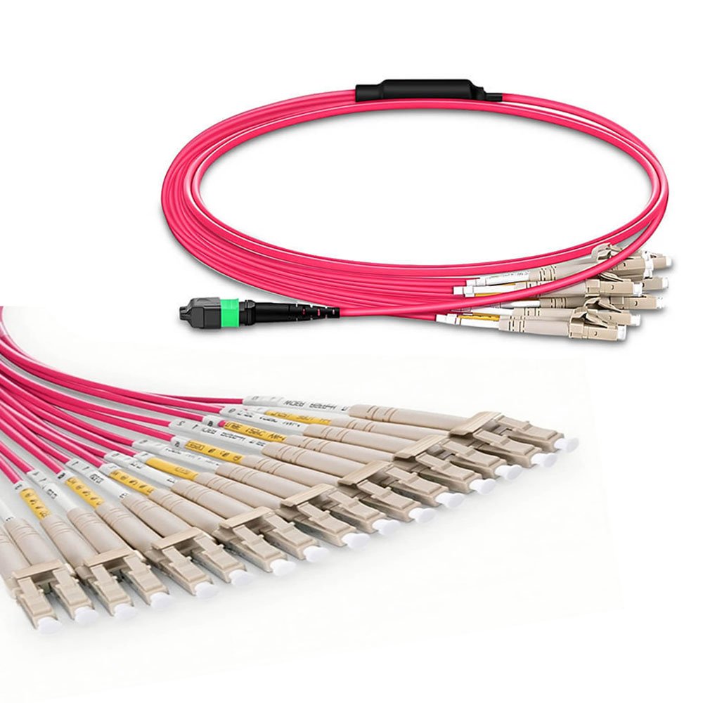
That physical mapping does not guarantee that a specific switch port can operate as eight independent channels. Confirm all of the following before releasing the cable drawing:
- The exact switch and transceiver part numbers.
- Whether the port supports the intended breakout mode.
- The fiber type and connector polish required by each optical interface.
- The transmit and receive lane positions on the MPO-16 interface.
- The LC channel numbering and end-A/end-B orientation.
- The total loss budget, including every mated connector pair.
Configuration matrix
| Design option | Fiber and interface | Jacket and pathway | Insertion-loss requirement | Density and rack impact | Best-fit use |
|---|---|---|---|---|---|
| Duplex LC patch cords | OS2 or project-approved multimode; LC duplex at both ends | LSZH, OFNR, OFNP or destination-specific rating | Set per channel and transceiver budget | More individual cords; rack density depends on panel and routing | Duplex optics and frequently changed equipment links |
| MPO-16 to 8 x LC duplex breakout | 16 fibers; one MPO-16 to eight duplex LC legs | Select from the approved pathway and fire requirement | Define per fiber in the approved drawing. A JHT MPO/MTP trunk specification lists a maximum of 0.35 dB for certain Elite configurations; confirm applicability to the ordered MPO-16 assembly | Consolidated trunk with eight serviceable LC channels; rack-unit density depends on the enclosure | Breakout, migration and equipment-to-distribution links |
| MPO-16 to MPO-16 trunk | 16 fibers; MPO-16 at both ends | Project-approved indoor data-center jacket | Allocate loss for each MPO mated pair and the complete channel | Lowest connector count when both endpoints are native MPO-16 | Direct parallel-optics links |
| VSFF MDC or SN system | Duplex or multi-fiber implementation according to the selected vendor ecosystem | Confirm cable, cassette and panel compatibility | Use the selected interface specification and channel budget | Can increase port density, but exact ports per rack unit are enclosure-specific | New designs standardized on a validated VSFF platform |
The entries in this matrix are architecture choices, not interchangeable connector substitutions. MPO-16, LC, MDC and SN interfaces require their own adapters, cassettes, polarity rules and cleaning tools.
JHT 16-fiber cable construction data
JHT NetFiber’s current indoor 16-fiber MPO cable sheet documents an OM4 construction with an LSZH jacket, a 10.0 mm overall cable diameter, 20D dynamic minimum bend radius and 10D static minimum bend radius. These values apply to that documented construction only. OS2, alternative jackets, different fanout structures or lower-diameter designs require a separate approved specification.
For any quotation, the controlled drawing should state:
- fiber type and fiber count;
- MPO-16 gender, key orientation and polish;
- LC polish, channel numbering and duplex clip orientation;
- overall length and manufacturing tolerance;
- breakout length, leg staggering and protective transition;
- cable outside diameter, jacket material and color;
- pull eye or protective sleeve requirement;
- label, serial-number and packaging plan.
Polarity management
Polarity must be documented as an end-to-end fiber map, not selected from a method name in isolation. Method A, B or C describes a cabling behavior, but the complete channel also contains adapters, cassettes, harnesses and transceiver interfaces.
For an MPO-16-to-LC breakout, the approved drawing should show every MPO fiber position and its corresponding LC channel. It should also identify transmit and receive directions, MPO gender, key orientation and the viewing direction used in the drawing. This prevents a correct cable from being installed against an incompatible cassette or port map.
Loss-budget control
The assembly acceptance limit must come from the complete optical channel budget. Count the MPO mated pair, every LC mated pair, the cable attenuation and any additional patching elements. Do not apply a generic 0.35 dB limit to every connector type or every product configuration.
JHT’s current MPO/MTP trunk documentation lists a maximum insertion loss of 0.35 dB for certain Elite connector configurations. For an MPO-16-to-LC product, the quotation and approved datasheet should specify the applicable connector grade, test wavelength, reference method and per-fiber limit. If the project requires a lower value, the feasibility and test method should be reviewed before the order is accepted.
Factory testing and documentation
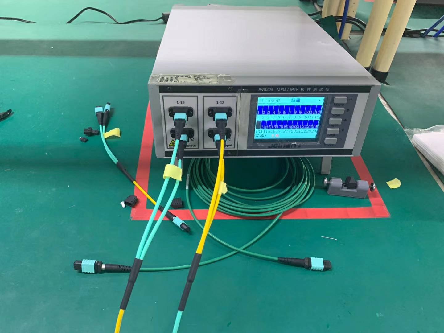
JHT’s current MPO/MTP trunk documentation describes factory pre-termination and testing. A project inspection plan for an MPO-16-to-LC breakout can include:
- visual end-face inspection using criteria aligned with IEC 61300-3-35;
- insertion-loss measurement for every fiber at the specified wavelength;
- return-loss measurement when required by the interface and contract;
- polarity and end-to-end fiber-map verification;
- connector gender, keying and LC-channel verification;
- overall length, breakout length and label inspection;
- packaging and drawing-revision checks.
IEC 61300-3-35:2022 states that visual inspection does not replace attenuation, return-loss or end-face-parameter measurements. A 3D interferometer report should therefore be listed as a separate requirement when the project needs ferrule-geometry evidence. OTDR testing is normally a link- or cable-plant diagnostic and should not be used as a substitute for insertion-loss measurement of a short passive assembly.
JHT should not claim ISO certification, CPR classification or 100% 3D interferometer inspection for this product unless the applicable certificate, product scope and agreed inspection plan are attached to the order documentation. OFNR, OFNP, LSZH and CPR are also not equivalent designations; the destination market and project specification determine which requirement applies.
Deployment controls for AI clusters
Airflow and cable congestion
Route the trunk away from switch exhaust paths and keep fanout transitions outside high-pressure cable bends. Validate tray fill with the actual cable outside diameter and bundle count. Use horizontal and vertical managers sized for the installed connector density rather than the nominal rack-unit count alone.
Rapid deployment
Pre-terminated assemblies reduce field termination, but speed depends on labeling and installation sequence. Pack assemblies by room, row, rack or cabinet, and match each label to the approved port map. Include spare channels and replacement assemblies only when the redundancy plan calls for them.
Repeat-order control
Record the approved drawing number, cable construction, connector components, fiber map, optical acceptance limits and label template. Any substitution should trigger a revised drawing and technical approval before production.
Engineering FAQ
Does an 800G link automatically require an MPO-16-to-LC breakout?
No. The Ethernet rate does not determine the cable assembly. Use an MPO-16-to-LC breakout only when the selected equipment interfaces and breakout architecture require one; a native MPO-16-to-MPO-16 or duplex-LC channel may be more appropriate in other designs.
How does Base-16 differ from Base-8 in a migration plan?
Base-16 uses sixteen fibers in one MPO-16 interface, while Base-8 groups parallel optics in eight-fiber increments. A migration plan must account for the transceiver lane count, connector keying, cassette design and whether unused fibers would be created. MPO-16 and MPO-12/Base-8 components are not physically interchangeable at the mating interface.
Is Method A, B or C enough to specify polarity?
No. Include the end-to-end fiber map, adapter orientation, connector gender and LC-channel numbering. The method name is useful only when every component in the channel follows the same documented design.
What bend radius should be used for a 16-fiber breakout trunk?
Use the value in the approved cable datasheet. One current JHT 16-fiber OM4 LSZH construction specifies 20D during installation and 10D after installation, where D is the cable diameter; other constructions may differ.
RFQ checklist
Send the following information for engineering review:
- switch and transceiver part numbers;
- end-A and end-B interface;
- fiber type and required breakout mode;
- MPO-16 gender, key orientation and polish;
- LC channel map and polarity drawing;
- overall length, fanout length and quantity;
- pathway, jacket and destination-market requirement;
- channel loss budget and required acceptance limits;
- inspection and test-document requirements;
- labels, serial numbers, packing sequence and drawing revision.
Send your cable specification to JHT NetFiber for configuration review and quotation.
Standards and technical references
- IEEE P802.3df material describing 800GBASE-DR8 as eight single-mode lanes with reach up to at least 500 m
- IEC 61300-3-35:2022 for visual inspection of fiber-optic connector interfaces
- ANSI/TIA-942-C Telecommunications Infrastructure Standard for Data Centers
- SENKO MPO-16 connector overview for high-density and 800G applications


2 Comments