Why AI Data Centers Need High-Density and Rollable Ribbon Fiber Cables
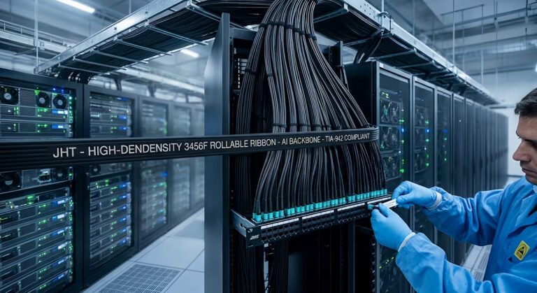
The bottleneck in an AI data center is not only bandwidth. As GPU clusters scale, the physical fiber plant must carry more optical links through finite racks, trays, conduits and campus pathways. High-density fiber cables address the space problem. Rollable ribbon addresses both packing density and high-count fiber handling by allowing flexible ribbon units to compact inside the cable while remaining suitable for mass fusion splicing.
This does not mean every AI facility needs the highest possible fiber count. Network topology, optical interface, redundancy, route length, growth plan and maintenance model determine the requirement. The useful question is whether a cable design solves a measurable pathway, splicing or expansion constraint.
This guide is written for data center engineers, structured cabling designers, integrators and procurement teams comparing cable architectures for AI/HPC backbones. For a product-focused specification and QA checklist, also see JHT NetFiber’s high-density rollable ribbon cable sourcing guide.
Why AI Data Centers Create a Fiber-Density Problem
GPU clusters generate heavy east-west traffic between compute nodes, accelerator fabrics, storage and network tiers. Leaf-spine or Clos architectures increase the number of switch-to-switch paths, while redundant fabrics create separate routes for availability. Moving from 400G toward 800G and future 1.6T systems changes the number and type of optical links, but the physical result is consistent: more ports can mean more backbone fibers and more cable routes.
There is no universal multiplier for how much more fiber an AI data center needs. Fiber count varies with rack topology, oversubscription, transceiver architecture, breakout strategy, redundancy and whether links are duplex or parallel. A defensible design begins with a port-and-link schedule, not an assumed ratio.
Once those links are mapped, the pressure moves into the physical layer: rack pathways, overhead trays, underfloor routes, inter-building ducts, campus conduits and splice enclosures. Capacity can be limited by cable outside diameter, allowable fill, bend radius, pulling space, closure volume and the number of splices a crew can prepare and test.
The Real Bottleneck: Pathway Space, Not Just Bandwidth
Traditional planning often starts with port count, data rate and distance. AI data center fiber cabling must also account for fibers per pathway, cable OD, tray and conduit fill, service-loop space, minimum bend radius, pulling or blowing limits, splice-tray capacity and room for future additions.
Engineering insight: Adding more cables is not always equivalent to adding more capacity. Once tray and conduit space become constrained, cable density becomes a design parameter.
Cable diameter affects more than fill calculations. It influences reel size, cable mass, pulling setup, pathway separation, turning clearance and how much working room remains at entrances and splice locations. A smaller cable can improve route utilization, but only when its tensile, crush, bend and environmental characteristics match the installation method.
The route should be surveyed before the cable is released. Record duct inner diameter, existing occupancy, bends, pull points, tray loading, entry seals, closure dimensions and the longest practical installation section. High density can recover pathway capacity, but it cannot compensate for an unverified route.
What Is a High-Density Fiber Cable?
A high-density fiber cable is not defined only by a large fiber count. The useful engineering measure is how many usable fibers can be deployed within a limited cable cross-section and pathway while preserving optical, mechanical, installation and service requirements.
Higher density may come from reduced-diameter coated fibers, optimized core geometry, rollable ribbon units, compact strength members, dry water-blocking materials or an optimized jacket. A specific cable does not necessarily use all of these features. The approved drawing and datasheet must identify the actual construction.
Density also has an operational side. Fiber identification, ribbon mapping, splice organization, cleaning, inspection, testing and restoration must remain manageable. Higher fiber density can reduce cable volume, but poor fiber management can create a different operational problem.
What Is Rollable Ribbon Fiber?
Traditional flat ribbon arranges fibers side by side and bonds them continuously into a relatively rigid strip. It supports mass fusion splicing, but its preferred bend direction and stacked geometry can limit how tightly ribbon units conform inside some cable cores.
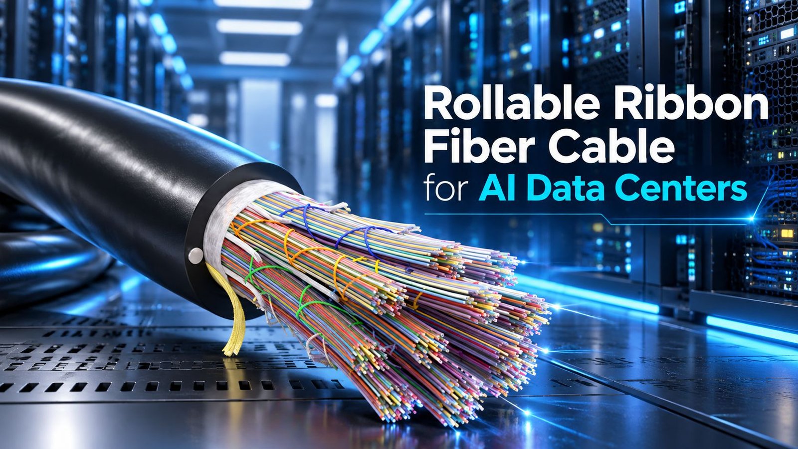
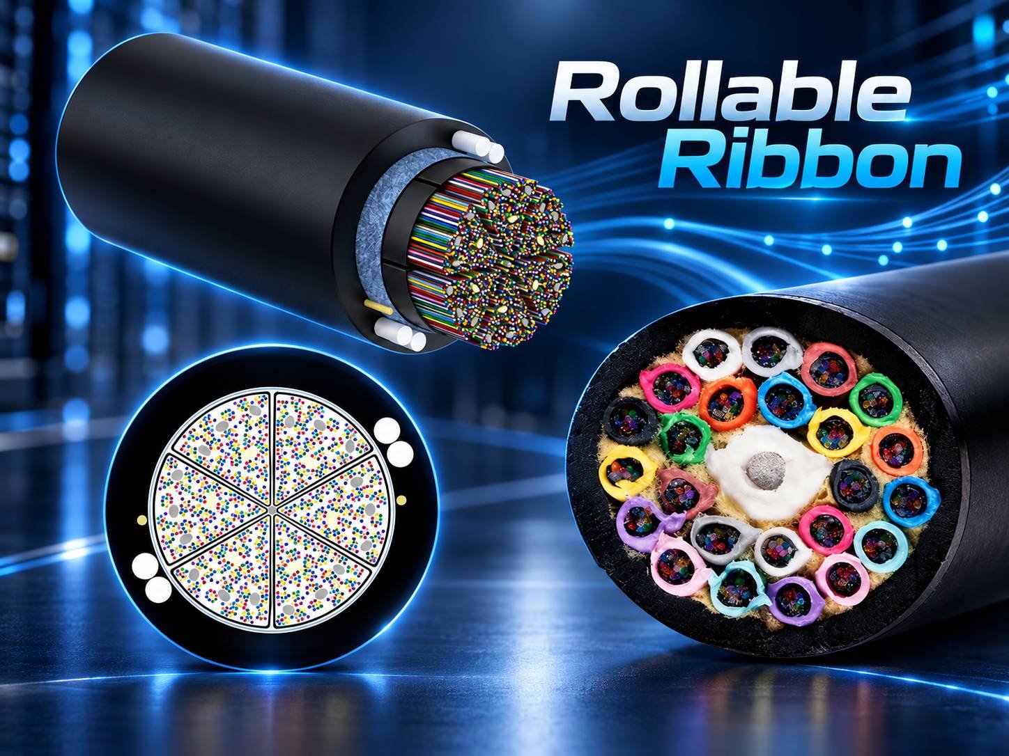
Rollable ribbon—often described as intermittently or partially bonded ribbon—connects adjacent fibers at discrete bonding points rather than continuously encapsulating the full strip. The flexible unit can roll or conform inside the cable, then return to an ordered ribbon arrangement for preparation and mass fusion splicing. Where the design permits, individual fibers can also be separated for breakout or repair.
The International Telecommunication Union describes partially bonded ribbon as a configuration that adds transverse flexibility so the ribbon can be rolled into small core structures, while retaining parallel fibers and mass-splicing capability. Ribbon dimensions, separability and strippability are covered through referenced IEC test methods in ITU-T L.101. Actual bonding patterns still vary by cable design.
Why Rollable Ribbon Fits AI Data Center Backbones
1. More Fibers in Limited Pathways
Flexible ribbon units can occupy cable-core space efficiently, increasing the number of fibers that can be routed through a constrained conduit, tray or campus duct. This is most valuable when pathway expansion is difficult, disruptive or expensive. The benefit must be checked against the proposed cable OD and the route’s allowable fill.
2. Smaller Cable Diameter at High Fiber Counts
For a given fiber count, an optimized rollable-ribbon design can support a smaller outside diameter than a less compact construction. Alternatively, a fixed pathway may carry more fibers. The outcome depends on fiber coating diameter, ribbon arrangement, strength members, water blocking, armor, jacket and fire-rating construction; no single reduction percentage applies to every design.
3. Faster High-Count Splicing
Single-fiber fusion treats one fiber per splice cycle. Mass fusion prepares and joins an ordered ribbon unit in one cycle, reducing the number of fusion operations needed for a high-count backbone. The project advantage grows at high splice counts, but preparation, ribbon alignment, cleaving, sleeve handling, tray loading and testing still consume labor.
4. Easier Scaling Between Data Halls
Rollable ribbon is primarily a backbone architecture, not merely a rack patch-cord format. It can support data hall interconnects, building-to-building links, entrance facilities, meet-me rooms, main distribution areas and horizontal distribution areas where many fibers must cross shared pathways.
5. Better Use of Existing Infrastructure
Brownfield facilities often have occupied ducts and trays but limited options for new construction. A denser cable may create additional usable fiber capacity inside an existing route. Procurement should compare this with the cost and risk of new pathways, while checking pulling tension, bend radius, duct condition and closure compatibility.
200 μm vs 250 μm Fiber in High-Density Cables
The 200 μm and 250 μm values describe the approximate coating diameter, not the optical core or the standard 125 μm cladding. Reducing coating diameter can increase packing density without claiming better optical performance. ITU technical material on reduced-diameter coated fiber notes the density benefit while also identifying handling and microbending considerations; see ITU-T GSTR-SDM.
| Item | 200 μm class | 250 μm class |
|---|---|---|
| Coating diameter | Reduced-diameter coating around standard optical fiber | Conventional coating diameter |
| Packing-density potential | Higher potential where the cable design supports it | Traditional density; also used in some high-density designs |
| Cable OD effect | Can support a smaller OD for a given fiber count | Depends on the complete cable construction |
| Splicing and preparation | Requires compatible stripping, cleaving, holders and ribbon pitch | Widely established tooling and work practices |
| Best-fit question | Is maximum pathway density worth the tooling and handling requirements? | Does conventional tooling and field familiarity outweigh the density gain? |
Specify coating diameter only after confirming splicing equipment, ribbon holders, field tools, connectorization method, project standards and crew capability. Mixing 200 μm and 250 μm workflows can require controlled spacing or transition preparation. The supplier should show how the proposed ribbon pitch is handled from cable preparation through splice protection.
12-Fiber vs 16-Fiber Rollable Ribbon
Twelve-fiber ribbon is mature and widely understood. Sixteen-fiber ribbon is increasingly relevant in very high-count installations because it can place more fibers in one ribbon unit and can align with some Base-16 connectivity architectures. Neither format should be selected from the Ethernet speed label alone.
| Decision factor | 12-fiber ribbon | 16-fiber ribbon |
|---|---|---|
| Mass-fusion potential | Up to 12 fibers per compatible ribbon splice cycle | Up to 16 fibers per compatible ribbon splice cycle |
| Field familiarity | Broadly established | Requires verified 16-fiber tooling, holders and procedures |
| Connectivity relationship | Common in many established backbone systems | May align with selected Base-16 connectivity designs |
| Selection basis | Backbone grouping, splice plan, patching and operations standard | Backbone grouping, splice plan, patching and operations standard |
| Key risk | Assuming every 12-position connector uses all ribbon fibers identically | Assuming 800G automatically requires 16-fiber ribbon |
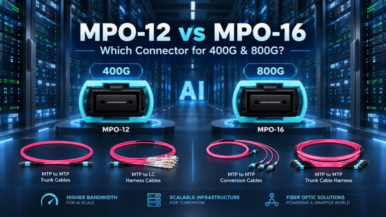
A project should compare ribbon count with closure capacity, splice-tray layout, fiber numbering, restoration procedures and the equipment-side connector architecture. For the transceiver side of the decision, use the separate guide to MPO-12 vs MPO-16 for 400G and 800G.
Mass Fusion Splicing: Where the Labor Advantage Comes From
The advantage comes from reducing fusion cycles, not eliminating the rest of the job. A single-fiber workflow joins one fiber per cycle. A compatible 12-fiber ribbon can present up to 12 fibers together; a compatible 16-fiber system can present up to 16. The Fiber Optic Association explains the distinction between single-fiber and ribbon mass fusion in its fusion-splicing reference.
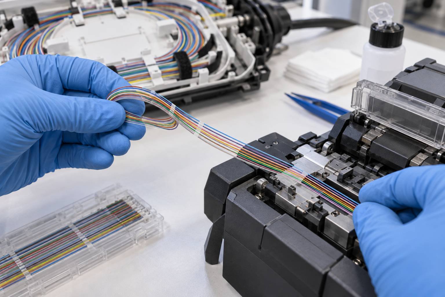
Overall project time still depends on cable opening, unit identification, ribbon preparation, coating removal, cleaning, cleaving, alignment, splice protection, tray loading, OTDR or insertion-loss testing, documentation and crew experience. A 12-fiber or 16-fiber splice cycle is not the same as making the entire project 12 or 16 times faster.
Before mobilization, verify that the splicer, ribbon holders, stripper, cleaver, heat-shrink sleeves and tray system support the selected coating diameter, ribbon pitch and fiber count. Trial preparation on the approved cable sample is more useful than relying on a generic labor assumption.
Rollable Ribbon vs Traditional Ribbon vs Loose Tube
| Feature | Loose Tube | Traditional Flat Ribbon | Rollable Ribbon |
|---|---|---|---|
| Fiber density | Low to high, depending on construction | High with stacked flat ribbons | High potential through flexible ribbon packing |
| Mass fusion | Possible after ribbonizing or with suitable units | Native ribbon workflow | Native workflow when the design and tools are compatible |
| Routing flexibility | Good individual-fiber flexibility | More rigid preferred bend behavior | Flexible transverse behavior |
| Individual fiber access | Generally familiar | Requires ribbon separation | Possible where the design permits; confirm method |
| High-count splice efficiency | Lower without ribbonizing | High | High, with additional preparation discipline |
| Mid-span access | Often familiar to field crews | Design-dependent | Design- and procedure-dependent |
| Cable OD potential | Varies widely | Compact but constrained by ribbon stack | Can reduce OD for a given count, depending on construction |
| Field familiarity | Broad | Established in ribbon environments | Training and tooling must be confirmed |
| Best fit | Flexible access and conventional operations | High-count systems using rigid ribbon workflows | Pathway-constrained, high-count backbones with planned mass fusion |
Loose tube may remain the better choice when crews frequently access individual fibers, mid-span work is common or ribbon tooling is unavailable. Traditional ribbon can be suitable where flat ribbon handling and existing closures are already standardized. Rollable ribbon is strongest when high density and high-count splicing solve a defined project constraint.
Where High-Density Rollable Ribbon Makes the Most Sense
- AI data center campus backbones with many inter-building fibers
- Data hall interconnects and high-count entrance facilities
- Hyperscale backbone routes with constrained conduits or trays
- High-count splice locations designed for ribbon trays and mass fusion
- Brownfield routes where new pathway construction is limited
- Projects reserving fiber capacity for future 800G or 1.6T migrations
- Backbones that transition through high-density patch panels to equipment-side connectivity
These are candidate conditions, not automatic approvals. The selected cable still needs a route calculation, installation method, splice plan, test plan and termination design.
When Rollable Ribbon May NOT Be the Best Choice
- Low fiber-count links where density brings no pathway benefit
- Routes requiring frequent individual-fiber mid-span access
- Small projects without compatible mass-fusion tooling or trained crews
- Existing splice closures or trays that cannot manage the ribbon count and service loops
- Maintenance teams whose identification and restoration standard is built around loose fibers
- Installations where a pre-terminated fiber trunk cable solves the requirement more simply
- Routes where cable OD, weight or bend characteristics do not improve the real constraint
High density should solve a physical-layer constraint, not simply be selected because the fiber count sounds impressive. A less dense cable with familiar access and repair procedures may produce a lower operational risk for some facilities.
Indoor, Outdoor and Fire-Rating Requirements
Procurement must define whether each segment is indoor, outdoor or indoor/outdoor. Inside buildings, the required OFNP, OFNR, LSZH or CPR classification depends on the installation zone, jurisdiction and local code. No single rating is mandatory worldwide. Verify the permitted cable marking and supporting documentation for the destination project.
For reference, UL’s optical-fiber cable marking guide lists North American designations including OFN, OFNR and OFNP. European CPR classification and documentation follow a different framework. The project specification and authority having jurisdiction control the final choice.
Outdoor and campus routes may additionally require water blocking, UV resistance, armor, rodent protection, duct or direct-burial construction, or suitability for pulling, blowing or jetting. These features affect diameter and mass, so the density comparison must use the complete cable—not a bare fiber-count figure.
What Procurement Teams Should Specify
A supplier should be able to reconstruct the intended route and splice architecture from the RFQ. Use the following JHT NetFiber sourcing checklist.
A. Network Requirement
- Application and facility zone
- Required fiber count and reserve strategy
- Current data rate and planned migration
- Route type, endpoints and distance
- Redundancy and pathway separation requirements
B. Fiber
- Single-mode or multimode and applicable fiber standard
- 200 μm or 250 μm coating class
- 12F or 16F ribbon where applicable
- Fiber and ribbon identification scheme
- Any bend-insensitive or project-specific fiber requirement
C. Cable
- Indoor, outdoor or indoor/outdoor construction
- Maximum cable OD target based on route study
- Tensile, crush and minimum bend requirements
- Water blocking, armor and rodent protection
- Jacket material, fire rating and required markings
D. Installation
- Pulling, blowing, tray or duct installation method
- Duct inner diameter, current occupancy and allowable fill
- Route bends, pull points and maximum installation section
- Reel size, pulling eye and handling requirements
- Service-loop and entrance-space constraints
E. Termination
- Field splice, mass fusion or pre-terminated architecture
- MPO/MTP, LC or other project interfaces
- Breakout map, polarity and equipment-end requirements
- Splice closure and tray compatibility
- Acceptance testing and loss-budget method
F. Documentation
- Cable datasheet and approved construction drawing
- Fiber and ribbon identification schedule
- Attenuation and mechanical test requirements
- Fire-rating documents where applicable
- Packing, reel, length-marking and test-report format
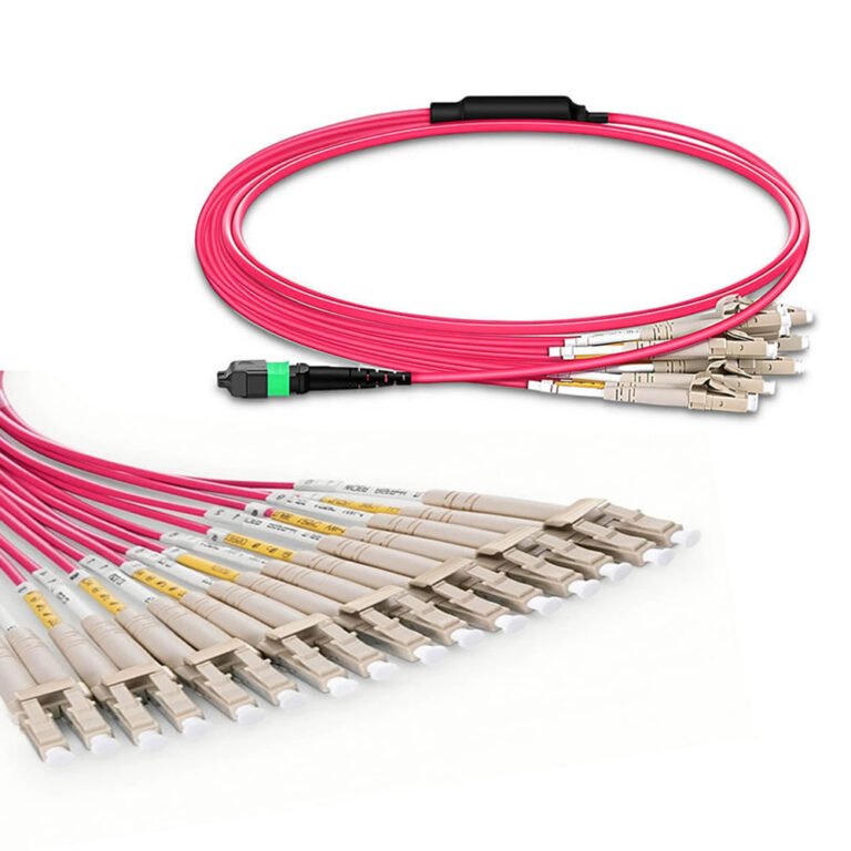
When the optical interface is not final, provide the transceiver part numbers and intended breakout mode. JHT NetFiber’s MTP/MPO connectivity, breakout cable and fiber patch cord pages show the equipment-side assembly categories that may connect to the backbone.
High-Density Fiber and MPO/MTP Are Related — But Not the Same Thing
Cable construction and connector architecture are different layers. High-density cable construction defines how fibers are packaged, protected and routed through a pathway. MPO/MTP connectivity defines how groups of fibers terminate and connect at equipment or patching interfaces.
A rollable-ribbon backbone may be field-spliced, factory pre-terminated, transitioned to MPO/MTP or LC, or landed in cassettes and patch panels. The correct architecture depends on route length, installation access, allowable mated pairs, polarity, maintenance model and transceiver ports.
Do not assume a 16-fiber ribbon requires an MPO-16 equipment interface, or that an MPO-12 connector defines a 12-fiber backbone grouping. Map the backbone, splice units and equipment interfaces separately, then document every transition.
Frequently Asked Questions
What is rollable ribbon fiber cable?
Rollable ribbon fiber cable uses flexible ribbon units in which adjacent fibers are connected at intermittent or partial bonding points instead of being continuously encapsulated in a rigid flat matrix. The units can conform inside a compact cable core and return to an ordered arrangement for mass fusion splicing. Bonding pattern, fiber count and separability depend on the cable design.
Why do AI data centers need high-density fiber?
AI data centers can require many east-west optical links between GPU clusters, switching tiers and storage. More links increase backbone fiber counts while rack, tray, conduit and campus pathway space remains finite. High-density cable can place more usable fibers within that limited space, provided installation, bend, splice and maintenance requirements are also satisfied.
Is rollable ribbon the same as intermittently bonded ribbon?
The terms are often used for the same general architecture: flexible ribbon fibers joined at spaced bonding points. They should not be treated as a single identical construction across every supplier. An RFQ should specify ribbon fiber count, coating diameter, pitch, separability, mass-fusion method and identification scheme rather than relying only on the product name.
Is rollable ribbon better than loose tube fiber?
Not universally. Rollable ribbon is attractive for pathway-constrained, high-count backbones and planned mass fusion. Loose tube can be simpler for lower counts, frequent individual-fiber access, mid-span work or teams standardized on conventional tooling. Compare route capacity, splice strategy, restoration practice, closure compatibility and technician experience.
Can rollable ribbon be mass fusion spliced?
Yes, when the ribbon architecture, coating diameter, pitch, holders and splicing equipment are compatible. The flexible unit is prepared into an ordered ribbon for cleaving and fusion. Mass fusion reduces the number of splice cycles, but cable opening, cleaning, protection, tray loading, testing and documentation still determine total project labor.
What is the difference between 200 μm and 250 μm fiber?
The values describe the approximate coating diameter around the standard optical fiber, not the optical core or cladding. A 200 μm coating can improve packing density, while 250 μm workflows are widely established. Selection should consider cable design, microbending control, stripping, cleaving, holders, ribbon pitch and field standards—not an assumption of better optical performance.
Why use 16-fiber ribbon?
A 16-fiber ribbon can present up to 16 fibers in one compatible mass-fusion cycle and may align with selected Base-16 backbone or connectivity architectures. It requires verified tools, holders, trays and mapping procedures. It is useful only when those operational benefits fit the project; 12-fiber ribbon remains a mature option.
Does 800G require 16-fiber ribbon?
No. Ethernet speed does not define the backbone ribbon count. An 800G transceiver may use one MPO-16, two traditional MPO interfaces, duplex connectivity or another implementation. Choose the cable and ribbon architecture after confirming transceiver part numbers, optical lanes, equipment interfaces, backbone grouping, breakout plan and migration strategy.
Can rollable ribbon be terminated with MPO/MTP connectors?
Yes, a rollable-ribbon backbone can transition to MPO/MTP connectivity through factory termination, fan-out, cassettes or field-spliced pigtails, depending on the design. The ribbon grouping and connector fiber count are not automatically identical. Confirm polarity, pinning, polish, channel mapping, insertion-loss budget and test method for every transition.
Is rollable ribbon suitable for indoor data centers?
It can be, but the cable must have the correct indoor or indoor/outdoor construction and fire rating for the installation zone and local code. Verify OFNP, OFNR, LSZH or CPR requirements as applicable, along with cable OD, bend radius, smoke and flame documentation, tray loading and compatibility with indoor pathways and closures.
What should I specify when requesting a high-density fiber cable?
Provide the application, fiber count, route, length, duct or tray constraints, fiber standard, coating diameter, ribbon count, cable OD target, tensile and crush requirements, minimum bend radius, water blocking, armor, jacket and fire rating. Also define installation method, splice architecture, termination interfaces, labeling, test reports, reel information and delivery location.
When should I use loose tube instead?
Consider loose tube for low or moderate counts, frequent individual-fiber or mid-span access, smaller projects without mass-fusion equipment, or maintenance teams standardized on loose-fiber closures and restoration methods. Loose tube may also be preferable when high density creates no pathway benefit. The decision should follow the route and operating model.
Building Fiber Capacity for the Next AI Upgrade
AI physical infrastructure planning should not begin with the maximum available fiber count. It should follow a traceable sequence: network architecture → required optical links → future growth → pathway capacity → fiber count → cable density → splice strategy → termination architecture.
Rollable ribbon is valuable when it solves a measured density or deployment constraint. Confirm the route, splicing workflow and maintenance model first; then compare cable drawings, test requirements and installation documentation before releasing the order.
Planning a High-Fiber-Count Data Center Backbone?
Send JHT NetFiber your fiber count, route, duct or tray constraints, installation environment, cable length, fire-rating requirement and termination plan. We can review the cable construction and help define a suitable high-density configuration before quotation.
Technical References
- ITU-T L.101: optical fibre cable construction, ribbon types and referenced IEC tests
- ITU-T GSTR-SDM: reduced-diameter coated fiber and density considerations
- Fiber Optic Association: fusion and ribbon mass splicing
- UL optical-fiber cable marking guide
Technical references checked September 24, 2026. Cable constructions, standards and equipment capabilities change; verify the current project specification and supplier documentation before procurement.