

MTP/MPO Connectivity Systems for High-Density Data Center Links
Build a coordinated multi-fiber link with trunk cables, breakout assemblies, patch cords, cassettes, panels, adapters and connectors selected as one system.
Design the complete link, not an isolated component
A reliable MTP/MPO channel depends on more than the cable. Fiber mode, fiber count, connector gender, key orientation, polarity method, enclosure layout and the interfaces at both ends must work together. This product center helps you move from link architecture to the correct component family.
Plan the optical path
Define the equipment interfaces, backbone route, conversion points and patching locations before selecting assemblies.
- OS2, OM3 or OM4 fiber direction
- Base-8, Base-12 or other required fiber count
- Direct-connect or cassette-based architecture
Control compatibility
Confirm polarity, male or female connector configuration, end-face polish and the installation method across the complete channel.
- Polarity Method A, B or C
- Key-up and key-down orientation
- Factory test records and port labeling requirements
MTP/MPO Product Families
Choose a family to review construction options, typical applications and RFQ information.
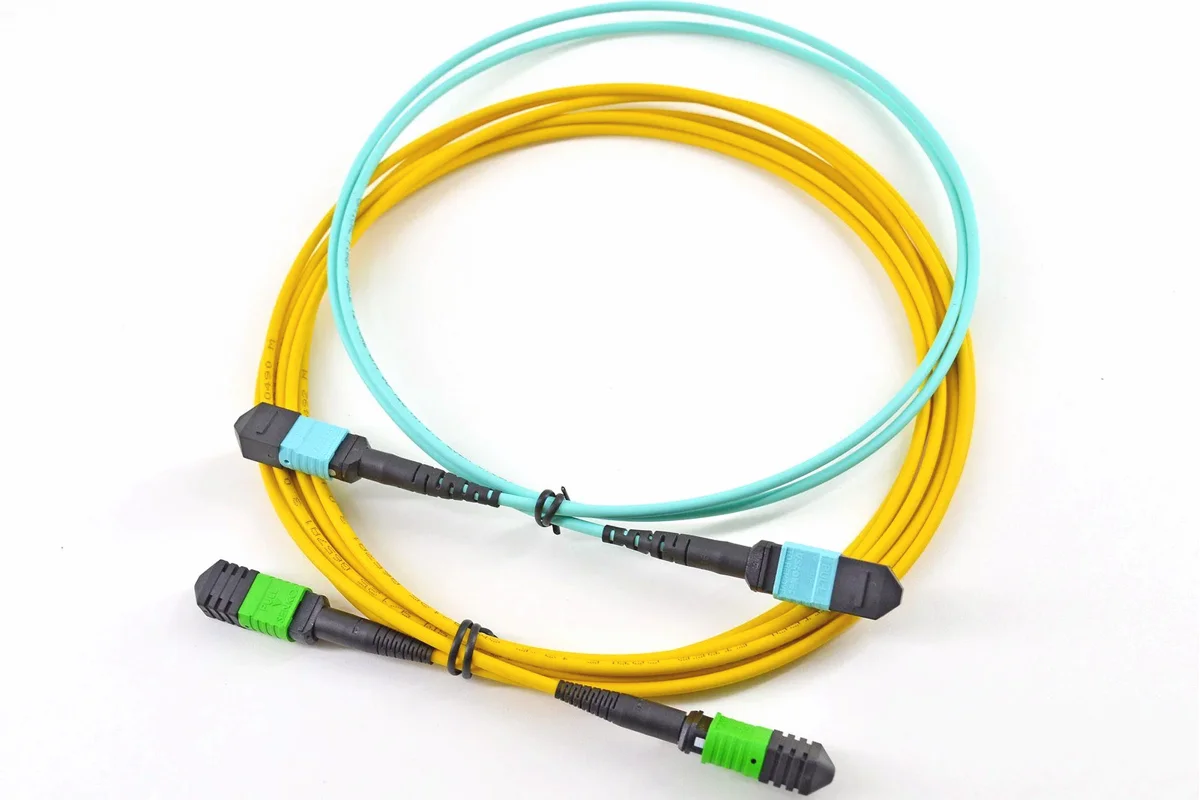
MTP/MPO Trunk Cables
High-density backbone assemblies for rack-to-rack, zone and equipment distribution links.
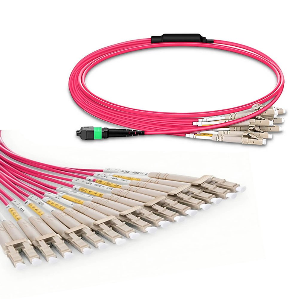
MTP/MPO Breakout Cables
Multi-fiber conversion assemblies that fan out an MTP/MPO interface to LC or other discrete connectors.
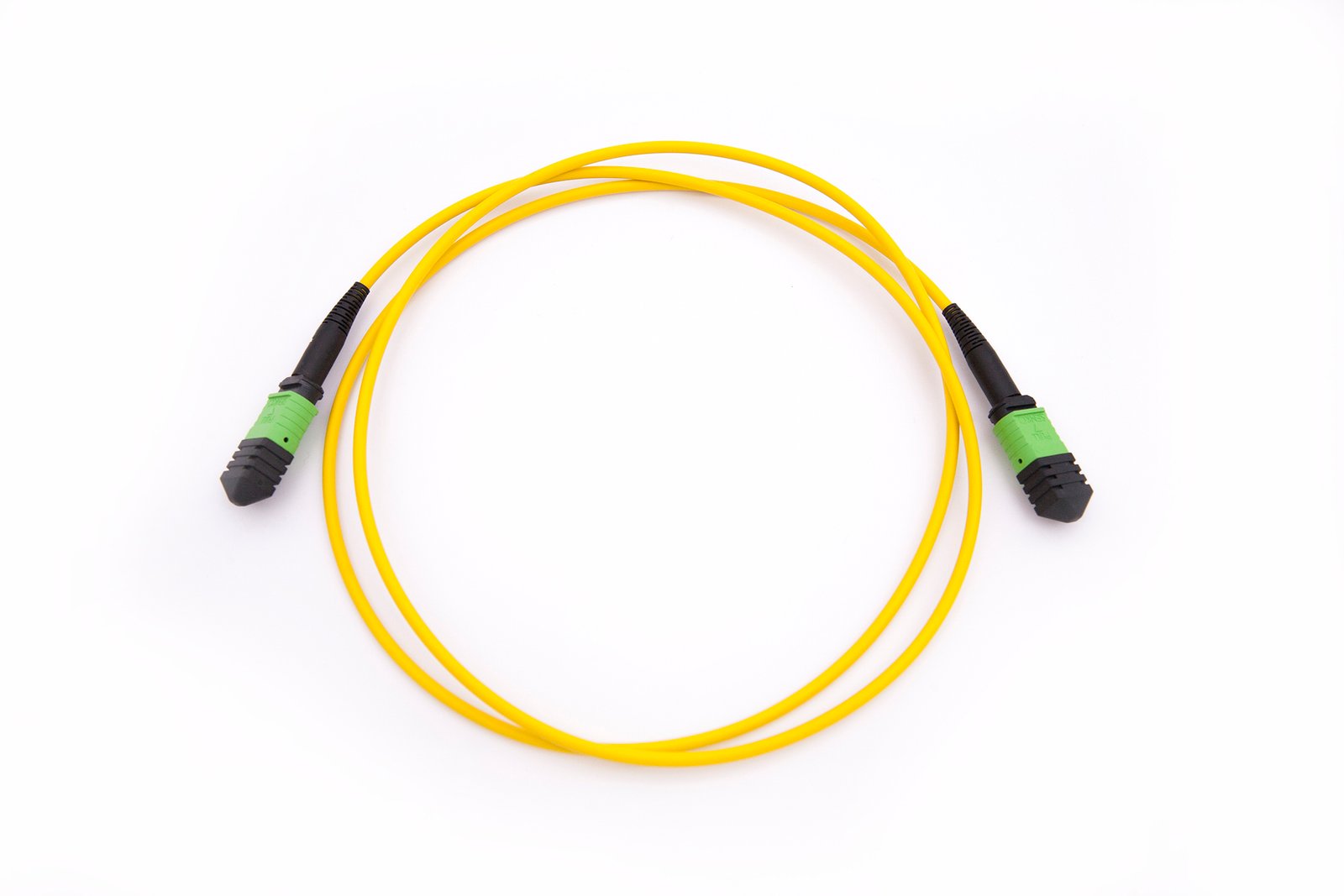
MTP/MPO Patch Cords
Short multi-fiber jumpers for equipment, cassette and panel interconnection where interface compatibility is already defined.
MTP/MPO Cassettes
Modular transition points that convert a multi-fiber backbone into manageable duplex ports.
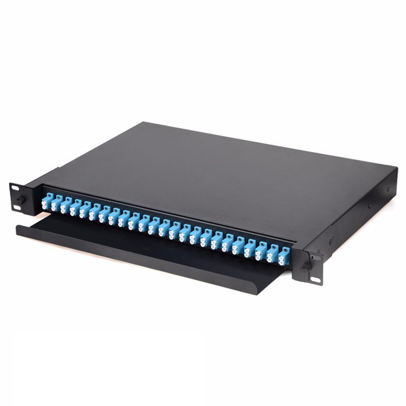
Fiber Patch Panels
Rack and enclosure platforms for cable entry, routing, cassette installation and front-port management.
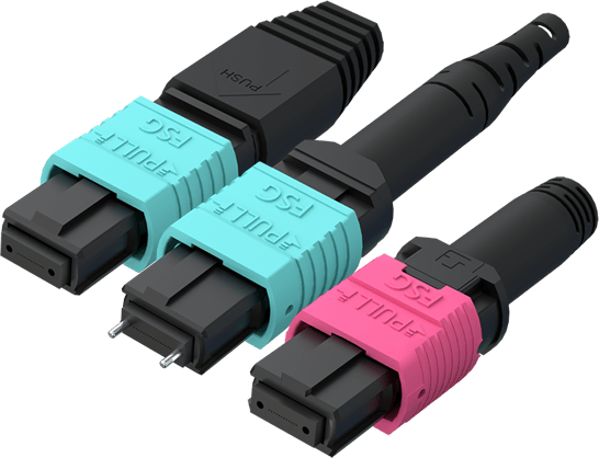
Adapters & Connectors
Interface components for mating, maintenance and assembly workflows within the MTP/MPO channel.
A practical MTP/MPO selection sequence
1. Define both end interfaces
List the transceiver, switch, cassette or panel interface at each end. This determines whether the link stays multi-fiber or converts to duplex connectors.
2. Choose the architecture
Use trunks for backbone distribution, breakout assemblies for direct conversion, and cassettes when modular front-port patching is preferred.
3. Confirm fiber and count
Specify fiber mode, channel speed direction, fiber count and any spare-fiber requirement.
4. Verify polarity and gender
Document polarity across every mated component. Confirm connector gender and key orientation before production.
5. Set installation details
Add length, pulling-eye needs, cable construction, breakout length, labeling and packaging instructions.
6. Define acceptance records
State the test method and documentation required for receiving inspection and link commissioning.

Where each component sits in the link
Trunks carry the high-density backbone. Cassettes or breakout assemblies convert the multi-fiber interface when duplex equipment ports are used. Patch cords complete short equipment and cross-connect links, while panels protect routing, slack and connector access.
For a usable quotation, send a simple end-to-end link sketch. Include connector type at both ends, fiber mode and count, polarity, cable length, jacket or installation environment, labeling and test-report needs. For MPO-16 breakout planning, use the 800G engineering guide as a lane-mapping and RFQ checklist.
MTP/MPO System Questions
When should I use a trunk cable instead of a breakout cable?
Use a trunk when both ends remain on multi-fiber interfaces or connect through cassettes. Use a breakout assembly when one multi-fiber connector must fan out to discrete equipment ports.
What does an MTP/MPO cassette do?
A cassette provides a protected modular transition from a multi-fiber backbone to front-facing duplex ports, simplifying moves, adds and changes.
Why must polarity be checked end to end?
Each cable, adapter and cassette affects transmit-to-receive mapping. A correct individual component can still create a failed channel if the full polarity plan is inconsistent.
Are MTP and MPO the same?
MPO describes the multi-fiber connector interface. MTP is a branded MPO connector implementation. Compatibility still depends on fiber count, gender, key orientation, polish and polarity.
What information is needed for a quotation?
Provide the two end interfaces, fiber mode and count, polarity, gender, length, cable construction, breakout details, labeling and required test documentation.