MPO-12 vs MPO-16: Which Fiber Connector Do You Need for 400G and 800G?
Short answer: choose the connector from the transceiver interface—not from the speed label. A 400G link may use MPO-12, MPO-16 or duplex connectivity. An 800G link may use one MPO-16, two MPO-12 interfaces, duplex connectors or another vendor-defined arrangement.
Recommended decision sequence: transceiver part number → optical interface → lane architecture → fiber count → polarity → cable assembly.
For procurement teams and network engineers, this distinction prevents a common and expensive mistake: ordering a cable because it is labeled “400G” or “800G” without verifying the optical ports at both ends. The same Ethernet rate can be delivered by different optical technologies, reach classes and connector formats.
This guide compares MPO-12 and MPO-16 for modern data center links, including 400G DR4, 400G SR8 and 800G DR8 examples. It also explains how to document the result in an RFQ. For the broader component family, see the MTP/MPO connectivity system.
What Is an MPO-12 Connector?
MPO-12 is the traditional 12-position multi-fiber connector format. The ferrule provides 12 fiber positions, but a given optical application does not have to use all 12. Many parallel-optics links use only eight active fibers—commonly four transmit and four receive—while the remaining positions are unused.
That is why MPO-12 is not the same thing as Base-12. MPO-12 describes the connector interface and ferrule positions. Base-12 describes how fibers are grouped in a cabling system. An MPO-12 connector can participate in an eight-fiber optical application, and a Base-8 design may still use a traditional MPO-format connector.
MPO-12 is widely found on parallel-optics transceivers, pre-terminated fiber trunk cables, cassettes and equipment-side patching. Exact compatibility still depends on fiber type, polish, pinning, polarity and the optical specification.
What Is an MPO-16 Connector?
MPO-16 is a 16-fiber connector interface designed for applications that need up to 16 fibers in one ferrule. A common parallel-optics use is eight transmit lanes plus eight receive lanes, as seen in some 400G SR8 and 800G DR8 implementations.
MPO-16 is mechanically distinct from the traditional MPO format. Its keying is offset rather than centered, helping prevent an MPO-16 plug from being incorrectly mated with a traditional MPO-12 interface. US Conec identifies the MTP-16 format with standards including TIA-604-18 and IEC 61754-7-3/-7-4. See the US Conec MTP-16 connector overview.
MTP® is US Conec’s branded implementation of MPO technology; it is not a separate generic connector standard. In procurement documents, specify the actual interface and performance requirements rather than using “MTP” and “MPO” as if they automatically identify different fiber counts.
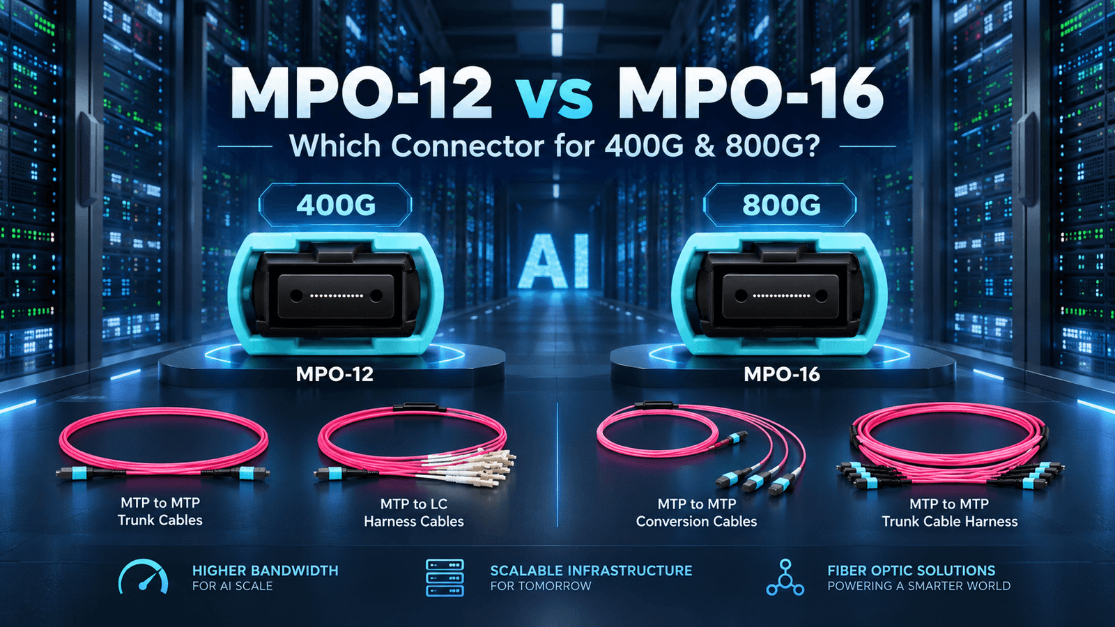
MPO-12 vs MPO-16: Quick Comparison
| Selection factor | MPO-12 | MPO-16 |
|---|---|---|
| Ferrule positions | 12 | 16 |
| Common active-fiber examples | 8 active fibers in many SR4/DR4 applications | 16 active fibers in some SR8/DR8 applications |
| Mechanical interface | Traditional MPO format with centered key | MPO-16 format with offset key |
| Direct mating | Mates only with the matching traditional MPO interface and correct gender/polish | Does not directly mate with MPO-12; use a designed transition |
| 400G examples | Some 400G DR4 modules; other designs may vary | Some 400G SR8 modules |
| 800G examples | Two MPO-12 interfaces on some 800G DR8 modules | One MPO-16 on some 800G DR8 modules |
| Best procurement rule | Verify the exact transceiver interface | Verify the exact transceiver interface |
Does 400G Use MPO-12 or MPO-16?
400G can use either—and it can also use duplex connectivity. The correct answer depends on the optical standard and the exact transceiver implementation.
400G DR4
Many 400GBASE-DR4 single-mode modules use four optical lanes in each direction and expose a traditional MPO interface with eight active fibers. An MPO-12 connector can house those eight active fibers. Cisco, for example, documents an MPO-12 interface for specific 400G DR4 modules. This does not mean every 400G transceiver uses MPO-12.
400G SR8
400GBASE-SR8 uses eight transmit and eight receive lanes over multimode fiber, so some SR8 modules use a 16-fiber MPO interface. Here, MPO-16 can place all 16 active fibers in one connector. Confirm whether the specific module requires APC or UPC polish and whether the vendor uses one or multiple optical ports.
400G Duplex Optics
Some 400G modules use wavelength-division multiplexing and a duplex LC interface. In that case, neither MPO-12 nor MPO-16 belongs at the transceiver port. The permanent backbone may still use parallel-fiber trunks with fiber cassettes, but the equipment-side connection presented to the module is duplex.
Does 800G Require MPO-16?
No. 800G does not automatically require MPO-16. MPO-16 is one valid implementation for 16-fiber parallel optics, but 800G products also exist with two MPO-12 interfaces, duplex interfaces and other architectures.
Example: 800G DR8 with MPO-16
An 800G DR8 module can map eight transmit lanes and eight receive lanes to one MPO-16/APC connector. This creates a compact single-interface solution, but it requires an MPO-16 cable plant or a deliberately engineered transition to the existing backbone.
Example: 800G Using Two MPO Interfaces
Other 800G DR8 modules split the optical lanes across two traditional MPO interfaces, often described as two 400G DR4 optical engines. Cisco’s official 800G OSFP transceiver data sheet shows both dual-MPO-12 and MPO-16 variants. The two variants need different cable assemblies even though both carry 800G.
Breakout architectures add another choice: an 800G port may be split into 2×400G or other supported child links. The connector on the high-speed end, the number of destination ports and the transceiver breakout mode all need to be specified. See breakout cable options for the equipment-side assembly concept.
Why the Transceiver Part Number Should Come First
The transceiver part number is the most reliable starting point because it identifies a vendor-specific implementation, not just a nominal Ethernet speed. Use this five-step selection sequence:
- Identify both transceivers. Record the exact manufacturer and part number for End A and End B.
- Read the optical interface. Confirm MPO-12, MPO-16, duplex LC or another connector, including APC or UPC polish.
- Map the lane architecture. Verify DR4, SR8, DR8, FR4 or another optical type, plus the number of transmit and receive lanes.
- Translate lanes into cabling. Determine active fiber count, straight-through or breakout mapping, polarity and pinning.
- Define the physical assembly. Set fiber type, length, jacket, pulling eye, branch lengths, labeling, testing and quantity.
Skipping Step 1 turns the cable into a guess. Two products marketed as “800G” may require completely different connectors, polarity maps and breakout assemblies.
MPO-12 vs MPO-16 for Data Center Backbone Design
Separate the permanent backbone from the equipment-side connection. The backbone is expected to serve multiple hardware generations, while equipment cords and transition modules can change when transceivers change. This separation gives migration planners more options than replacing the whole channel every time a new interface appears.

- Permanent backbone: prioritize reach, fiber capacity, insertion-loss budget, pathway use, panel density, documentation and future repatching.
- Equipment side: match the exact port interface, breakout map, pinning, polish and short connection length.
- Transition layer: use tested cassettes, modules or conversion harnesses only when their mapping and loss fit the complete channel.
A backbone built with high-density patch panels and modular cassettes may preserve cabling investment while equipment-side interfaces evolve. However, every added mated pair consumes loss budget, and not every Base-8 or Base-12 system maps cleanly to a 16-fiber application.
MPO-16 to MPO-12 Migration and Breakout
MPO-16 and MPO-12 do not directly mate. Migration normally uses a purpose-designed conversion assembly, breakout harness or cassette that maps the MPO-16 channels to the required traditional MPO or duplex ports. The mapping must follow the transceiver lane assignment—not merely the connector’s fiber count.
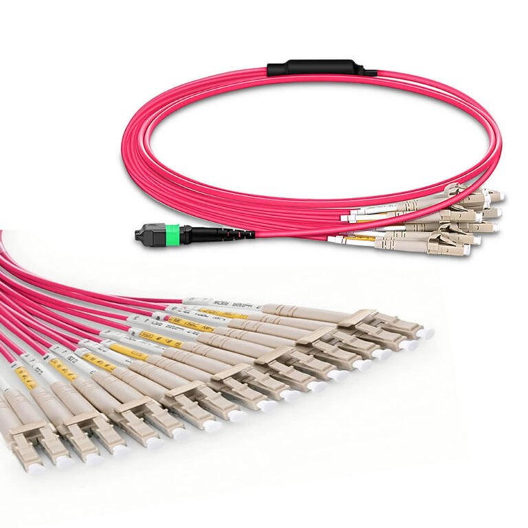
For an application-focused example, read MPO-16 to LC breakout trunk cables for 800G AI clusters. When a short equipment connection is required instead of a backbone trunk, an MTP/MPO patch cord may be the appropriate assembly form.
Before approving a migration assembly, verify channel numbering at both ends, loss budget, connector gender, adapter type, polish, branch lengths, port labels and test method. A mechanically connectable solution is not necessarily an optically correct solution.
What About MPO Polarity?
Polarity defines how transmit fibers at one end reach receive fibers at the other. Common methods are often called Type A, Type B and Type C, but the label alone is not enough for a complex channel. Cassettes, adapters, patch cords and trunks combine to create the end-to-end mapping.
For parallel-optics links, provide the required end-to-end channel map or the transceiver application plus the selected polarity method. If the link uses breakout legs, label every destination port and verify the mapping with a test plan before installation.
Male or Female MPO?
Male MPO connectors contain guide pins; female connectors do not. A correct mated pair needs one pinned side and one unpinned side. Transceiver receptacles are commonly unpinned, so the mating cable may need a pinned connector—but this must be confirmed from the module and adapter documentation.
Do not order “male-to-male” or “female-to-female” from habit. Define the mating interface at End A and End B, and account for any adapters or cassettes between them.
UPC or APC?
UPC and APC describe end-face polish. APC is angled and commonly identified by green components; UPC is flat-polished and often blue. They are not interchangeable. The transceiver specification determines the required polish, and both ends of every mated connection must match.
Some single-mode parallel-optics modules use MPO/APC, while many multimode applications use MPO/UPC. Treat that as a pattern, not a purchasing rule: verify the data sheet for each part number.
What Should Be Included in an MPO RFQ?
A useful RFQ should let the supplier reconstruct the complete link without guessing. Organize requirements into four groups:
1. Equipment
- End-A and End-B manufacturer and transceiver part numbers
- Switch, router or server port location and supported breakout mode
- Number of links and planned spare quantity
2. Optical Configuration
- Optical type and reach class, such as DR4, SR8 or DR8
- Connector interface at each end: MPO-12, MPO-16, LC or other
- Single-mode or multimode fiber, active fiber count and wavelength requirements
- Polarity method, channel map, connector gender and UPC/APC polish
3. Cable Construction
- Assembly type: trunk, patch cord, breakout harness or cassette module
- Installed length, branch lengths and length tolerance
- Jacket rating, cable diameter, bend-radius limits and pulling-eye requirement
- Connector protection, labels, serial numbering and packaging
4. Project Control
- Insertion-loss and return-loss test requirements
- Test wavelength, test direction and report format
- Applicable standards or customer specifications
- Delivery location, required date, approval samples and change-control contact
If any of these fields is unknown, send the transceiver data sheets with the RFQ and request a configuration review before quotation.
Practical Selection Guide
| Observed equipment interface | Likely assembly direction | What to verify before ordering |
|---|---|---|
| 400G DR4 with one MPO-12 port | MPO-12 trunk or patching; possibly MPO-to-duplex breakout for supported fan-out | Eight active fibers, APC/UPC, pinning, polarity, reach and breakout mode |
| 400G SR8 with one MPO-16 port | MPO-16 cable assembly | 16 active multimode fibers, polish, pinning, polarity and loss budget |
| 400G module with duplex LC | Duplex patch cord or cassette-presented duplex port | Fiber type, wavelength, connector polish and channel loss |
| 800G DR8 with one MPO-16 port | MPO-16 trunk, patch cord or engineered breakout | Port map, APC/UPC, single-mode reach, pinning and transition compatibility |
| 800G DR8 with two MPO-12 ports | Two correctly mapped MPO-12 connections or a vendor-qualified harness | Which MPO serves which lanes, polarity, labels and breakout support |
| Existing MPO-12 backbone to new MPO-16 equipment | Conversion cassette or harness after engineering review | Fiber utilization, mapping, added loss, panel density and future migration |
Frequently Asked Questions
Is MPO-12 always used for 400G?
No. Some 400G parallel-optics modules, such as certain 400GBASE-DR4 designs, use an MPO-12 interface with eight active fibers. Other 400G modules use MPO-16, duplex LC, or vendor-specific interfaces. Confirm the exact transceiver part number and its optical connector before selecting the cable.
Does 800G require an MPO-16 connector?
No. An 800G transceiver may use one MPO-16, two MPO-12 interfaces, duplex connectors, or another vendor-defined arrangement. The required cable follows the module interface and lane architecture, not the 800G label alone. Always check both ends of the link.
Can an MPO-12 connector plug directly into an MPO-16 adapter?
No. MPO-16 uses a different keyed interface from the traditional MPO format used for MPO-12. The mechanical formats are intentionally distinct, so direct mating is not the correct migration method. Use an engineered transition assembly, cassette, or breakout matched to the two interfaces.
Is MTP different from MPO?
MPO is the standardized multi-fiber push-on connector family. MTP is US Conec’s branded, high-performance implementation of an MPO connector. For an RFQ, specify the required interface, fiber count, key orientation, pinning, polish, and performance instead of treating MTP and MPO as unrelated connector standards.
What information is needed to quote an MPO cable correctly?
Provide the transceiver part numbers at End A and End B, optical connector interfaces, fiber type, link length, breakout requirement, polarity method, male or female pinning, UPC or APC polish, jacket rating, quantity, labeling, test-report requirements, and delivery destination.
How should I plan migration from MPO-12 to MPO-16?
Separate the permanent backbone from equipment-side connectivity. Existing Base-8 or Base-12 infrastructure may sometimes be retained with cassettes or conversion assemblies, while new MPO-16 links can be introduced where the optics require them. Validate loss budget, polarity, port mapping, density, and future transceiver plans before procurement.
Choose the Cable from the Optical Interface, Not the Speed Label
The defensible purchasing rule is simple: speed identifies the performance class; the transceiver identifies the cable interface. Start with the exact part number at each end, confirm the lane architecture and connector, then define polarity, pinning, polish and cable construction.
This process works for new 400G and 800G deployments, AI cluster buildouts and migrations from existing parallel-fiber backbones. It also produces an RFQ that suppliers can review without filling critical gaps with assumptions.
Need Help Matching the Cable to Your Transceiver?
Send JHT NetFiber your transceiver part number, End-A and End-B interfaces, fiber type, link length, breakout requirement and quantity. We can review the cable configuration before quotation.
Technical References
- US Conec FAQs: MPO and MTP connector terminology
- US Conec: MTP-16 Connector Solutions
- Cisco: 800G OSFP Transceiver Modules Data Sheet
- Corning: 10G to 800G data center optical connectivity guide
Technical references checked September 20, 2026. Product interfaces can change by vendor, hardware revision and reach option; verify the current transceiver data sheet before purchase.