
High-Density Rollable Ribbon Fiber Cable for AI Data Center Backbones
Executive summary. A high-density rollable ribbon fiber cable organizes intermittently bonded fiber groups into a compact backbone for data center pathways where fiber count, route space and splice workflow must be managed together. For a pre-terminated version, a project may specify connector acceptance targets such as insertion loss ≤ 0.35 dB per applicable MPO/MTP interface and return loss ≥ 60 dB for single-mode APC terminations, but those values do not describe bulk-cable attenuation and must be confirmed on the approved assembly drawing. Architecturally, the cable can carry high fiber counts between campus entrances, meet-me rooms, main and horizontal distribution areas, and spine-leaf zones while the selected transceivers and equipment-side assemblies determine whether the channel supports 400G or 800G optics.
Who this cable is for, and when not to specify it
This guide is for sourcing managers, infrastructure procurement engineers and structured-cabling contractors evaluating high-fiber-count backbone capacity. JHT NetFiber’s current rollable ribbon cable family presents a reference range of 144 to 3456 fibers across indoor, indoor/outdoor and outside-plant constructions. The exact fiber count, outside diameter, mass, tensile rating, bend limits and fire classification remain construction-specific.
- Use it when: the route needs a high fiber count, pathway space is constrained, 12-fiber identification supports the splice plan, and factory-controlled construction data can be approved before release.
- Do not select it by fiber count alone: a conventional loose-tube, solid-ribbon, micro cable or indoor distribution cable may be easier to route or terminate for a lower-count link.
- Do not treat it as an optics standard: the cable provides the physical medium; transceiver type, wavelength, reach, connector interface and end-to-end loss budget determine application compatibility.
Architectural role in AI data center backbones
High-density AI clusters increase the number of optical paths between switching tiers, GPU rows and inter-building distribution points. The permanent backbone should therefore be planned separately from equipment-side patching: the cable carries capacity through trays, risers or ducts, while splice hardware, MPO/MTP trunks, cassettes and LC or VSFF patching present the required interfaces at each end.
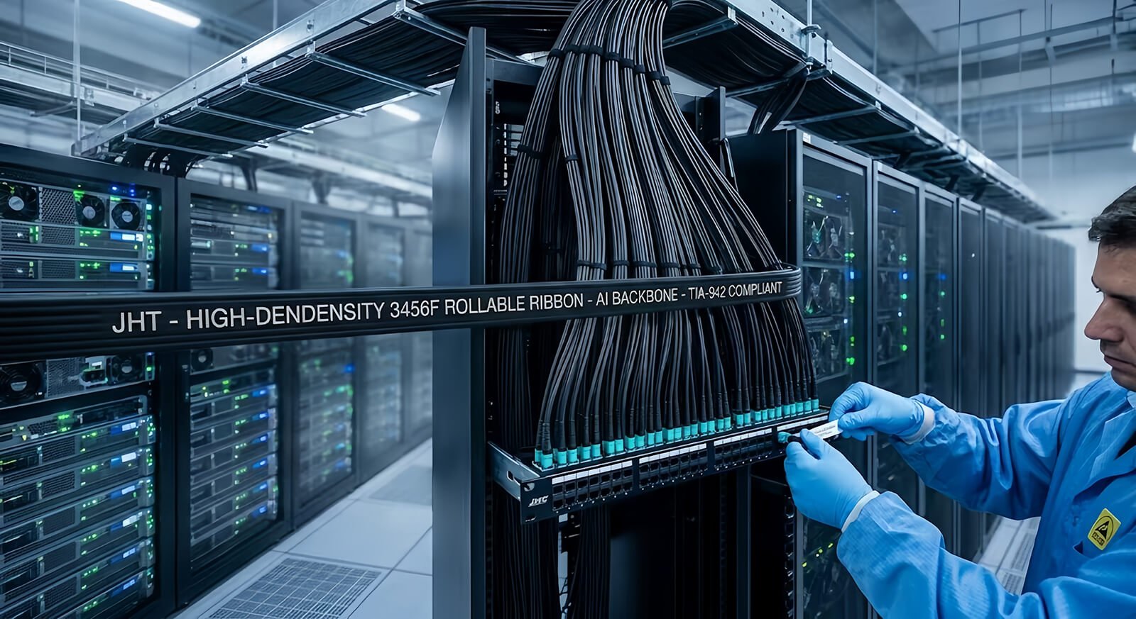
ANSI/TIA-942-C addresses telecommunications infrastructure for data centers and recognizes cabling, pathways, cooling and fire protection as connected design concerns. In procurement documents, identify the route by facility zones such as entrance room, main distribution area, horizontal or intermediate distribution area, equipment distribution area and cabinet row. Then show where the bulk cable is spliced, where it is connectorized and where equipment patch cords begin.
Space, weight and thermal impact: calculate before claiming savings
A smaller cable can release pathway area and reduce bundle mass, but a universal percentage saving is not credible without two approved constructions. Require suppliers to quote outside diameter in millimetres and mass in kilograms per kilometre for both the baseline and proposed cable. For a round cable, the nominal cross-sectional area is A = πD²/4; use this only as a comparison input, because real tray and conduit fill also depends on bundle geometry, separation rules, pulling clearance and local code.
| Procurement check | Baseline cable | Proposed high-density cable | Acceptance method |
|---|---|---|---|
| Fiber count and growth | Installed count plus spare capacity | Required count in one or more organized units | Approved fiber schedule and unit map |
| Outside diameter | Record actual D₁ in mm | Record actual D₂ in mm | Compare πD₁²/4 with πD₂²/4, then validate route fill |
| Cable mass | Record kg/km | Record kg/km | Check reel mass, tray loading and pulling plan |
| Minimum bend radius | Dynamic and static values | Dynamic and static values | Apply the larger requirement at bends, entries and storage loops |
| Maximum pulling tension | Cable-specific rating | Cable-specific rating | Pull calculation, grip method and route drawing |
| Rack airflow | Document existing obstruction | Model the proposed bundle and slack location | Visual inspection plus temperature/airflow validation after installation |
In 42U or 48U racks, do not place large service loops in front of switch intakes or exhausts. Keep the trunk transition and splice enclosure outside the most congested equipment zone, reserve vertical-manager capacity, and document the route through side channels or overhead trays. A compact backbone may improve airflow indirectly by reducing pathway obstruction, but rack thermal performance should be verified after cabling is installed rather than inferred from cable diameter alone.
Technical parameter matrix for RFQ comparison
| Parameter | Standard or baseline option | High-density/project option | Evidence required before purchase |
|---|---|---|---|
| Single-mode fiber | Project-approved OS2, commonly G.652.D | G.657.A1 or G.657.A2 where tighter bend performance is required | Named fiber specification, attenuation limits and approved bill of materials |
| Multimode fiber | OM4 for short-reach data center links | OM5 only where the optical design requires wideband multimode fiber | Transceiver reach table and channel-loss budget |
| Fiber organization | Loose tubes or conventional solid ribbon | Intermittently bonded rollable ribbon in identified 12-fiber groups | Cross-section drawing, color code and unit map |
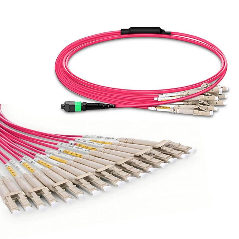
| Termination | Bulk or splice-ready cable | Stub, MPO/MTP, LC, MDC or SN ends only when supported by the architecture | End-A/end-B drawing, connector gender, polish and fiber map |
| Connector insertion loss | Contract-defined standard grade | Ultra-low-loss target such as ≤ 0.35 dB only for an applicable connectorized assembly | Per-fiber IL report, wavelength, reference method and acceptance limit |
| Return loss | Interface-specific requirement | ≥ 60 dB may be specified for qualifying single-mode APC terminations; UPC and multimode limits differ | Per-fiber RL report where contractually required |
| Cable OD and mass | Supplier datasheet values | Optimized construction selected against the pathway | Approved OD, kg/km, reel length and tolerance |
| Fire and jacket | LSZH or project-defined indoor material | CPR B2ca/Cca or UL OFNR/OFNP only when the exact construction carries the required evidence | DoP/CE or UL listing and cable marking matched to part number |
| Pulling protection | Standard reel and end cap | Factory pulling eye, protective sleeve or staggered breakout | Pulling-eye dimensions, rated load and installation method |
| Density and rack units | Defined by enclosure and splice hardware | High-count backbone feeding high-density panels | Panel capacity, splice-tray count, routing space and growth reserve |
Do not describe OM4 or OM5 as G.657.A2. OM4 and OM5 are multimode categories; G.657.A2 is a bend-insensitive single-mode fiber category. A procurement specification should keep fiber category, coating diameter, cable construction and connector polish as separate fields.
Rollable ribbon construction and splice workflow
Intermittent bonding connects adjacent fibers only at selected points, allowing the ribbon to roll into a compact bundle while retaining organized fiber groups. The structure can support mass-fusion workflow, but splice productivity depends on the selected fiber pitch, ribbon preparation, splicer, cleaver, holder, technician procedure and splice-tray capacity. Require a sample or method review when the contractor has not previously handled the proposed ribbon construction.
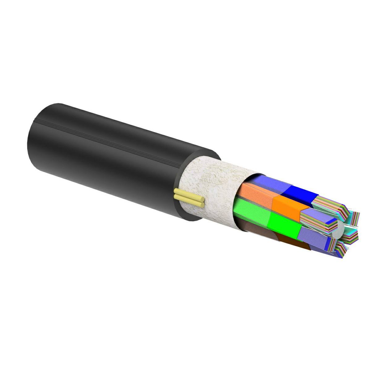
- Confirm whether the design uses 200 µm or 250 µm coated fibers and whether the intended mass-fusion tooling supports the selected pitch.
- Define 12-fiber group identification, subunit color sequence and splice-tray routing on the approved drawing.
- Allocate splice-closure and panel capacity for every planned group, including growth and restoration fibers.
- Verify cable access, mid-span access and water-blocking procedures when the route requires them.
Fire and safety compliance by destination market
LSZH, CPR and UL cable designations answer different questions and should not be used as synonyms. LSZH describes material behaviour related to smoke and halogen content; a CPR class describes reaction-to-fire performance for a declared European construction product; OFNR and OFNP are North American optical-fiber cable markings associated with specific installation spaces and listings.
European projects
For a project requiring CPR B2ca or Cca, request the exact Declaration of Performance, CE information, notified-body details where applicable, applicable harmonised specification and cable marking for the quoted construction. Do not accept a certificate for a different jacket, diameter or product family. IEC 60332 test references may support a technical file, but an IEC flame-test statement alone is not a substitute for the required CPR declaration.
North American projects
For riser or environmental-air spaces, specify the installation requirement and require the exact UL marking, such as OFNR or OFNP, on the cable or traceable product documentation. A generic LSZH jacket is not automatically suitable for a plenum, and a CPR class does not replace the listing required by the authority having jurisdiction.
GR-1435 and connector scope
Telcordia GR-1435 addresses single-mode multi-fiber optical connectors. It may be relevant when the backbone is supplied with MPO/MTP terminations, but it is not a stand-alone qualification for the bulk rollable ribbon cable. Cable construction, connector reliability and completed-assembly optical acceptance should appear as separate requirements.
Optical loss budgeting for 400G and 800G channels
The Ethernet speed printed on a switch does not define the cable. Start with the exact transceiver part numbers and medium: OS2 for single-mode applications or the specified multimode category for short-reach optics. Confirm wavelength, reach, lane count and equipment connector before deciding whether the backbone terminates by splice, MPO/MTP, LC, MDC or SN.
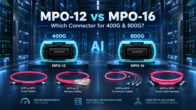
Keep three measurements separate in the purchase specification: fiber attenuation per kilometre, splice loss per event and connector insertion loss per mated pair or assembly interface. A ≤ 0.35 dB connector target and ≥ 60 dB return-loss target may be appropriate for a defined ultra-low-loss single-mode APC assembly, but neither value should be copied across all fiber types and connector polishes. For an MPO-16 equipment breakout, see the separate MPO-16 to LC breakout guide.
Sourcing and factory QA checklist
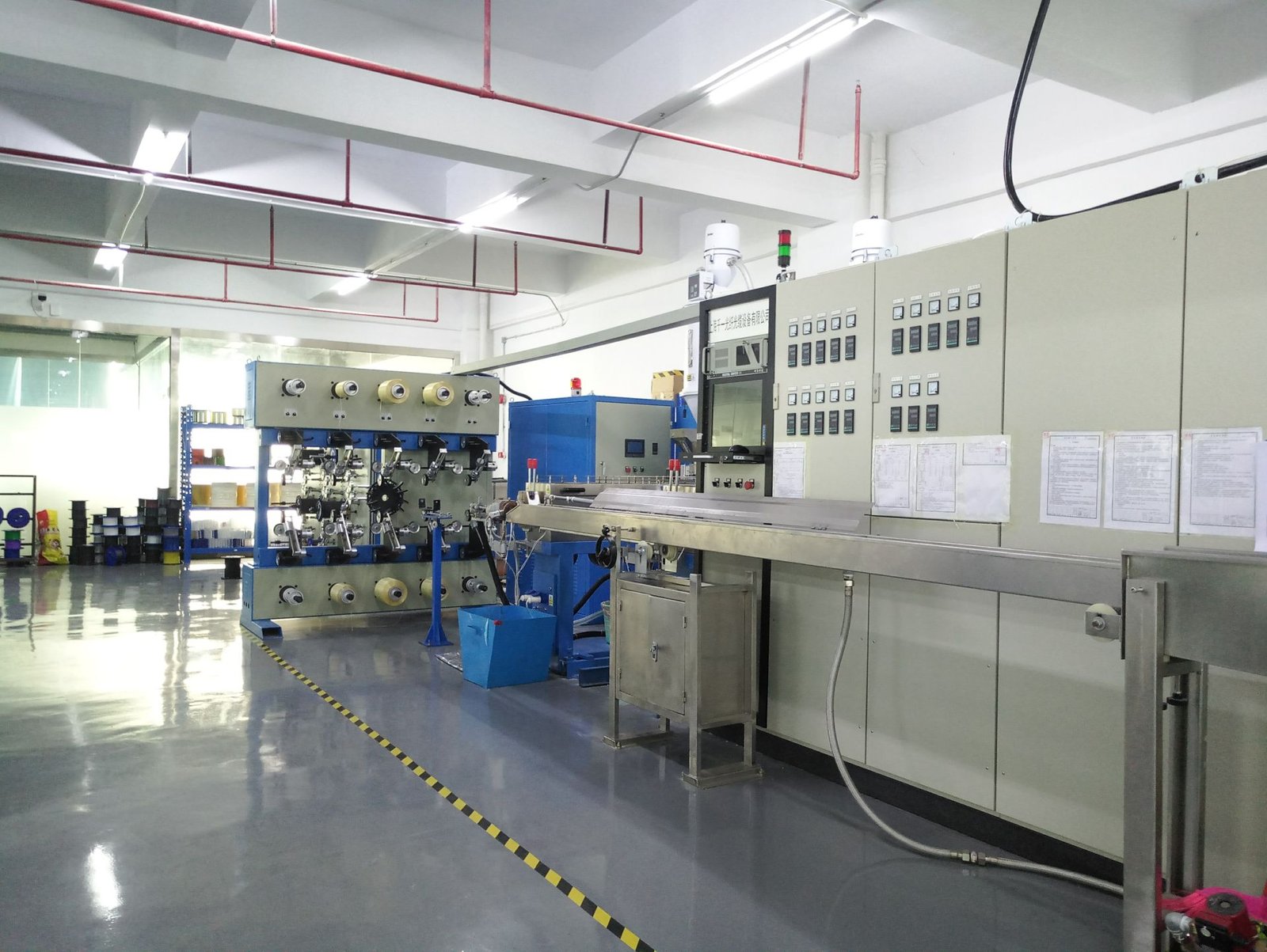
The inspection plan should distinguish cable manufacturing checks from connector-assembly checks. This prevents a shipment from appearing fully tested when only one layer was measured.
Cable manufacturing evidence
- Approved cross-section and construction drawing with revision control.
- Fiber count, subunit sequence, jacket marking and measured finished length.
- Outside diameter, mass, tensile and crush criteria specified for the construction.
- Dynamic and static bend-radius requirements, installation temperature and operating range.
- Attenuation measurement at the wavelengths required by the fiber specification.
- Reel identification, packing list and traceability to the production lot.
Connectorized assembly evidence
- End-A/end-B configuration, polarity or full fiber map and breakout-leg identification.
- 100% per-fiber insertion-loss measurement when included in the inspection plan.
- Return-loss results for the interfaces and wavelengths defined by contract.
- End-face inspection criteria aligned with IEC 61300-3-35.
- 3D interferometer inspection only when ferrule-geometry reporting is required and agreed before production.
- Overall and breakout lengths, tolerance, pulling eye, protective transition and label inspection.
OTDR traces are useful for installed links and long cable sections, but they are not a substitute for insertion-loss measurement of a short connectorized assembly. State which test method, launch and receive conditions, wavelength, reference method and report format will be accepted. If a report is required inside every carton, make that packaging rule explicit instead of assuming it from a general quality statement.
OEM/ODM configuration and repeat-order control
A repeatable OEM order needs more than a commercial part name. Freeze the cable construction, approved material list, drawing number, label template, reel or carton plan, test limits and document set. Private-label packaging should identify the customer-facing part number without removing manufacturing traceability needed for corrective action.
- Length: state nominal length, manufacturing tolerance, measurement reference and whether pulling-eye length is included.
- Breakout: define leg count, stagger sequence, leg length, protective tubing and transition dimensions.
- Reel and carton: define maximum reel mass, flange size, payout direction, moisture protection and packing sequence.
- Lead time: request prototype, drawing-approval, material-procurement and production stages separately; do not accept an unsupported universal quick-turn promise.
- Change control: require written approval before substituting fiber, jacket compound, strength member, connector component or packaging.
Procurement release checklist
- Route drawing, pathway dimensions and indoor/outdoor transition points.
- Fiber type, coating diameter, count, 12-fiber organization and spare-capacity plan.
- Cable OD, kg/km, minimum bend radii, pulling tension and installation method.
- Jacket material, exact fire classification and destination-market evidence.
- Bulk, splice-ready, stub or pre-terminated end configuration.
- Connector gender, polish, keying, polarity and full fiber map where applicable.
- Optical acceptance limits, wavelengths, reference method and report format.
- Drawing approval, sample approval, labels, private packaging and repeat-order controls.
Technical FAQ
How does high-density rollable ribbon cable solve polarity management across spine-leaf architectures?
The backbone cable preserves documented fiber groups and identification, but polarity is controlled by the complete terminated channel. The approved drawing must map every fiber through trunks, cassettes, adapters and equipment interfaces; the cable construction alone does not establish Method A, B or C.
What is the minimum bend radius under maximum pulling tension?
Use the dynamic bend radius and maximum pulling tension stated on the approved construction drawing. Do not infer these limits from fiber count or a generic cable family; the value changes with outside diameter, strength members, armor, jacket and installation method.
What test reports and documentation are provided inside each shipment carton?
Specify the approved drawing revision, reel or assembly identification, length record, optical test report, polarity or fiber map for terminated assemblies, inspection record, packing list and the exact compliance documents required by the destination project. A 3D interferometer report should be requested only for connectorized assemblies when it is part of the agreed inspection plan.
Send a reviewable cable specification
Send JHT NetFiber the route, fiber count, environment, termination plan, quantity and required evidence. Request a cable configuration review before releasing the purchase specification.
Standards and technical references
- ANSI/TIA-942-C, Telecommunications Infrastructure Standard for Data Centers
- IEC 60332-3-10:2018, vertical flame-spread test apparatus for bunched electric and optical fiber cables
- IEC TR 62222:2021, fire performance of communication cables installed in buildings
- European Commission overview of the Construction Products Regulation
- UL optical-fiber cable marking guidance for OFN, OFNR and OFNP types
- Corning technical overview of extreme-density ribbon cable design and mass-fusion workflow
- UL Solutions overview including GR-1435 multi-fiber connector testing
One Comment